Problem Statement
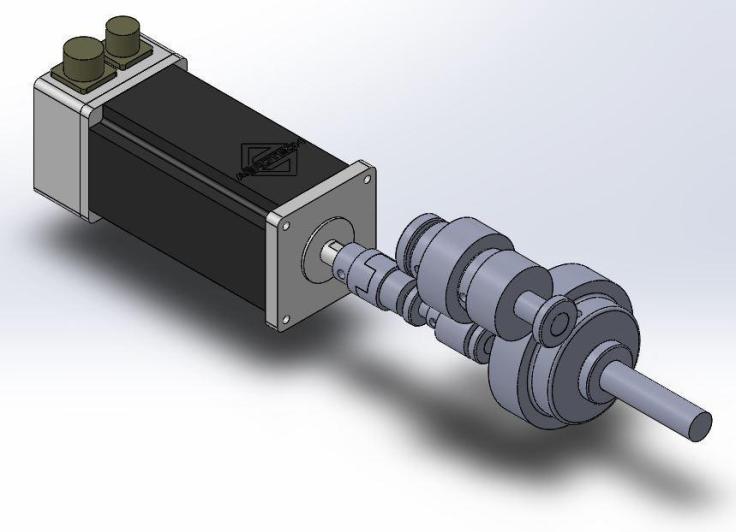
Design a power transmission system to connect a DC motor to its load. The motor is given in the motor catalog as BM1400. Create a transmission which will connect this motor and have a gear reduction with a total drive reduction of 5:1. The output shaft should be parallel to the input shaft.
Design Considerations
The operating conditions, duty cycle, and production quantity of this gear box was not specified in the problem statement. Because of these unknown factors, the gear box was designed to withstand maximum initial torque at startup of 209 lb-in as well as be able to withstand running at 130 lb-in at its maximum speed of 3000 RPM. In addition, all shafts were designed to be in infinite fatigue life or as high as possible, as well as the keys to last as long as possible without servicing. The gear box was also designed to be as compact as possible and easily detachable from the motor and the whole gear box to be easily assembled as well.
First, the gears were chosen to withstand the torque at each shaft and deliver the correct gear reduction. Next, the general arrangement of the parts was considered and then modeled in SolidWorks, refining the gear arrangement to optimize the key length and reduce the stresses the key will see by increasing its area. Next the gearbox was arranged to be in the most compact, yet accessible configuration.
Motor
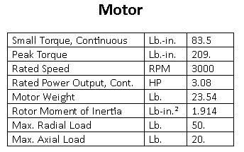
Table 1: BM1400 Motor Specifications
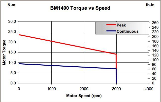
Figure 1: Motor Torque vs. Speed Curve
Gears
The following gears and their specifications are listed in Table 2 and 3 below.
The gear set that will be purchased from Boston Gear all contain standard 3/16” square keys cut into them from factory. In addition, Boston Gear also offers tapping of setscrews into all of their products. Every gear contains a standard 5/8” set screw to keep the gears from moving axially along the shaft.
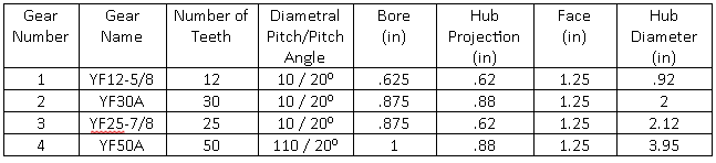
Table2: Gear Specifications

Table 3: Gear Load Ratings
Torque
Given the chosen gear teeth, startup, as well as running torque can be calculated:
- Shaft 1: 209 in-lb startup, 130 in-lb running
- Shaft 2: 522.5 in-lb startup, 325 in-lb running
- Shaft 3: 1,045 in-lib startup, 650 in-lib running
Shaft Analysis
AISI 1050, quenched and tempered at 400F was selected for shaft 1 and 3. The shaft diameter of shaft 2 was limited due to the gear bore, therefore , AISI 4340, quenched and tempered at 600F was selected in order to meet the design objectives given this constraint.
Fatigue calculations are made with the assumption that the motor loads the gearbox cyclically between 0 and 209 in-lb.
Shaft 1

Figure 2:Shaft 1 Geometry
- 1050 quenched and tempered at 400F Steel: Sy = 117 kpsi, Su = 163 kpsi, q = 0.8 [1]
- Torque = 209 lb-in start-up in repeated loading and 130 lb-in static loading
- Kt = 2.4
- Ktf = 2.12
- Kts = 3.25 [1]
- Ktsf = 2.80 [1]
- C_load = 1 (Von Mises)
- C_size = 0.910
- C_surf = 0.700 (Machined)
- C_temp = 1 (T < 840 deg. F)
- C_reli = 0.702 (99.99%)
The stress and loading were calculated using the below equations. Then, beam diagrams were used to determine the bearing reaction forces, shear, and moment diagrams of the shaft. Finally, the endurance limit, 1000 cycle material strength, Von Mises stress, and fatigue life were calculated.

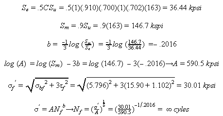
A similar procedure was used for shafts 2 and 3 for their loading, number of gears, and geometry. A summary of results can be found in Table X.
Shaft 2
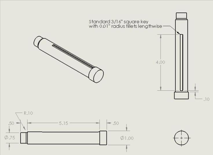
Figure 3: Shaft 2 Geometry
- 4340 quenched and tempered at 600F Steel: Sy = 230 kpsi, Su = 250 kpsi, q = 0.8 [1]
- Torque = 209 lb-in start-up in repeated loading and 130 lb-in static loading
- Kt = 2.5 [1]
- Ktf = 2.2 [1]
- Kts = 3.50 [1]
- Ktsf = 3.0 [1]
- C_load = 1 (Von Mises)
- C_size = 0.894
- C_surf = 0.679 (Machined)
- C_temp = 1 (T < 840 deg. F)
- C_reli = .0702 (99.99%)
Shaft 3
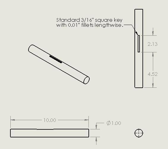
Figure 4: Shaft 3 Geometry
- 1050 quenched and tempered at 400F Steel: Sy = 117 kpsi, Su = 163 kpsi, q = 0.8 [1]
- Torque = 209 lb-in start-up in repeated loading and 130 lb-in static loading
- Kt = 2.8 [1]
- Ktf = 2.44 [1]
- Kts = 3.70 [1]
- Ktsf = 3.16 [1]
- C_load = 1 (Von Mises)
- C_size = 0.869
- C_surf = 0.700(Machined)
- C_temp = 1 (T < 840 deg. F)
- C_reli = 0.702 (99.99%)
Bearings
The bearings selected are the KP10A, KP12A, and KP16A. These bearings were chosen because they are able to withstand radial and thrust loads that will be much higher than the anticipated loading on the gears.
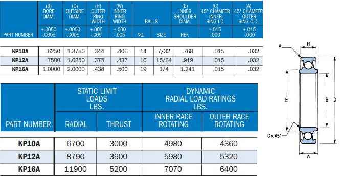
Table 4: Bearing Specifications and Load Ratings
Keys
Most components in this gear box are connect with keys and kept from moving axially with a set screw. The key length was maximized in order to reduce the amount of shear stress they will encounter. The material chosen is S-5 quenched and tempered at 400F. It is considered a tool steel that is used in repeated high stress conditions. This material was chosen to withstand the repeated direct shear in fatigue that they keys will endure.
- S-5 Steel quenched and tempered at 400F, Sy = 280 kpsi, Su = 340 kpsi, q = 0.8 [1]
- Key 1 and 2 have 209 in-lb static and 130 in-lb repeated loading
- Key 3 has 523 in-lb static and 325 in-lb repeated loading
- Key 4 has 1,045 in-lb static and 650 in-lb repeated loading
- Cload = 1 (Von Mises)
- Csize = 0.702
- Key 1 = 0.942
- Key 2 = 0.965
- Key 3 = 0.930 Note: Use .930 (lowest value)
- Key 4 = 0.959
- Csurf = 0.934 (Machined)
- Ctemp = 1 (T < 840 deg. F)
- Creli = 0.702 (99.99%)
- Ignore the bending in the key caused by the radial loading.
Key 1

Figure 5: Key 1 Geometry
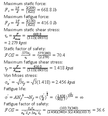
The following procedure was used for calculating the maximum shear stress, FOS in static and fatigue, and fatigue life for each key.
Key 2

Figure 6: Key 2 Geometry
Key 3

Figure 7: Key 3 Geometry
Key 4

Figure 8: Key 4 Geometry
Summary of Results
A summary of the static and fatigue stress, number of cycles to failure, FOS in static and fatigue loading is shown below.
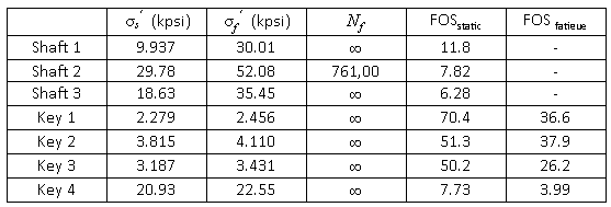
Table 5: Summary of results for shafts and keyways
The design of the gear box and materials chosen were chosen with the assumption that the motor was going to be worked to the peak of its possible performance and in the worst case conditions. Most of the parts are designed for infinite life in this type of service with the exception of shaft 2 which has finite life at a value of 761,600 cycles. This means that the shaft will require inspection at various intervals to check for surface crack and crack propagation. It is possible that this shaft will need to be replaced with time.
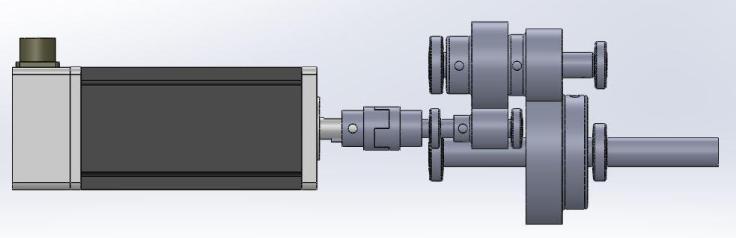
Figure 9: Gearbox side view
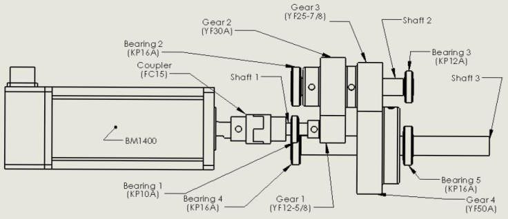
Figure 10: Component naming and assembly drawing
Biblyography
[1] Norton, Robert L. Machine Design: An Integrated Approach. 5th ed. Upper Saddle River: Pearson
Education, 2014. Print.
