Purpose
The purpose of this machine is to accurately simulate the full range of motion that a light-rail bogie can experience. This includes translation in all three directions as well as rotation about all three principal axes. The machine will perform accelerated life testing on the cable and their routing in order to:
- Optimize cable routing, length and shielding
- Generate a maintenance schedule from accelerated life testing
- Serve as a test fixture capable of bogie motion simulation for future needs
Contributions
Mechanical:
- Determine optimal geometry to meet project requirements
- Design system components using Solidworks using parametric modeling methods
- Worked in conjunction with other Engineers performing classical stress and fatigue analysis, and implemented component modifications based on their results
- Utilized Solidworks integrated FEA to further refine component design and material selection
- Used mass properties for motor and amplifier sizing
- Assisted with the manufacturing of frames, spherical tabs, motor mounts and welding fixtures
Controls:
- Develop and implement inverse kinematics, mathematical models, and simulations
- Program prototype models
- Implement algorithm to parse track geometry and turn into GCode
- Motion verification and validation testing
Contributors
This system was brought from concept to reality through the tireless efforts of my team members and friends:
- Jeremy Kearney
- Brian Tracy
- Ken Bruner
- Will Foster
Design Constraints and Requirements
Motion Requirements:
- Maximum expected roll: +/- 2.5°
- Maximum expected pitch: +/- 2.5°
- Maximum expected yaw: +/- 20.0°
- Maximum expected longitudinal translation (X): +/- 10mm
- Maximum expected lateral translation (Y): +/- 50mm
- Maximum expected vertical translation (Z): +/- 75mm
- Must be able to move in all 6 Degrees of Freedom simultaneously
Other Requirements
- Continuous operation for approximately 500 hours per life cycle
- Infinite life (up to 108 cycles) for all components (bearings, frame, actuators, etc…)
- Support a frame structure the size of the light-rail bogie (2m x 1.5m)
- Full turn-key solution to be completed in two academic semesters
- Capable of being manufactured using CSUS machine shop
- Low maintenance
- Utilize off the shelf industrial control interface
Mechanical Design Overview
The frame and platform are planar frames using 2″x2″x0.125″ square tubing. Welded to them are boxed motor mounts were constructed of 1/4″ steel plate and tabs for holding the upper spherical joints. The push-rods are 36″ long and made of 1.25″OD 1/4″ wall thickness.
The rotary arms were designed to withstand the stress from both bending and torsional loads imposed from the pushrods. The geometry/profile was refined using Solidworks FEA, minimizing weight, reducing stress concentrations, utilize available low cost materials, and reduce the likelihood of fatigue failure . The length of the rods were derived from the mathematical simulations. Diameter and wall thickness were derived from classical beam and buckling analysis.
Mounting tabs are welded to the upper platform for mounting an extruded aluminum frame that the cable routing would later be mounted to.
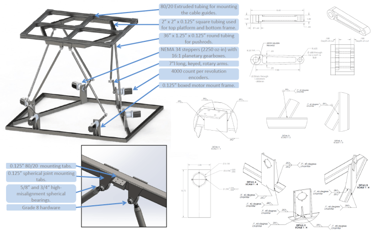
Overview of the various components of the fatigue tester
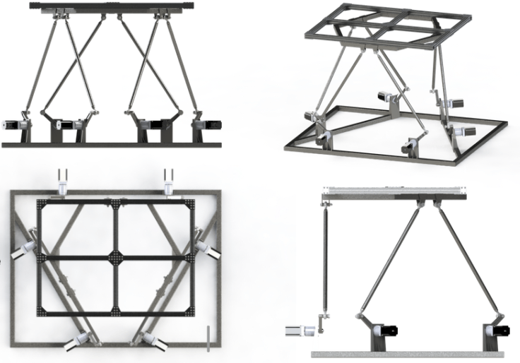
Solidworks rendering of the final design
Youtube video from motion testing
Controls Design Overview
Critical to the function of this machine was the inverse kinematics, which can be derived by defining two inertial frames. A translation and rotation matrix can then be applied to the frame of the platform and the linear distance to the mounting points can be computed. Finally, geometry can be used to solve for rotary angles with pushrod and rotary arm lengths as constants.


Diagrams showing how the real or virtual actuator length, and rotary angle can be calculated utilizing translation vectors and rotation matrices applied to the platform reference frame
Matlab simulation was heavily employed for optimizing the geometry that defines this system to meet the project requirements. In addition 3D printing was critical to developing a scale model for testing the mathematics and other aspects of the control.


Graph showing a Matlab simulation of a combined linear and rotational move (left) and scale model used for validation testing (right)
During validation testing, it was found that pure yaw motion resulting in errors in unexpected displacement in the Z direction. As this was the most critical motion of the simulation, this behavior was characterized and the control algorithm added a fitting function to compensate.
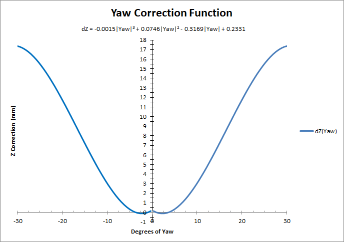
Fitting function for correcting Z height as a function of yaw.
